Intro
Who:
What:
make 1:1 connections and a flat 30x30mm mounting pattern for entire video system
include it’s own power filter to ensure reliability 2024-04-22 Video System Power Changes
what this isn’t (at least initially) is us designing a vtx or other difficult circuits ourselves.
start simple for 80% of the win then go complicated later for the final 20% of advantage at competition.
stay focussed on the goal of advantage at competition and alleviating integration hell
As simple as possible, solve integration problems.
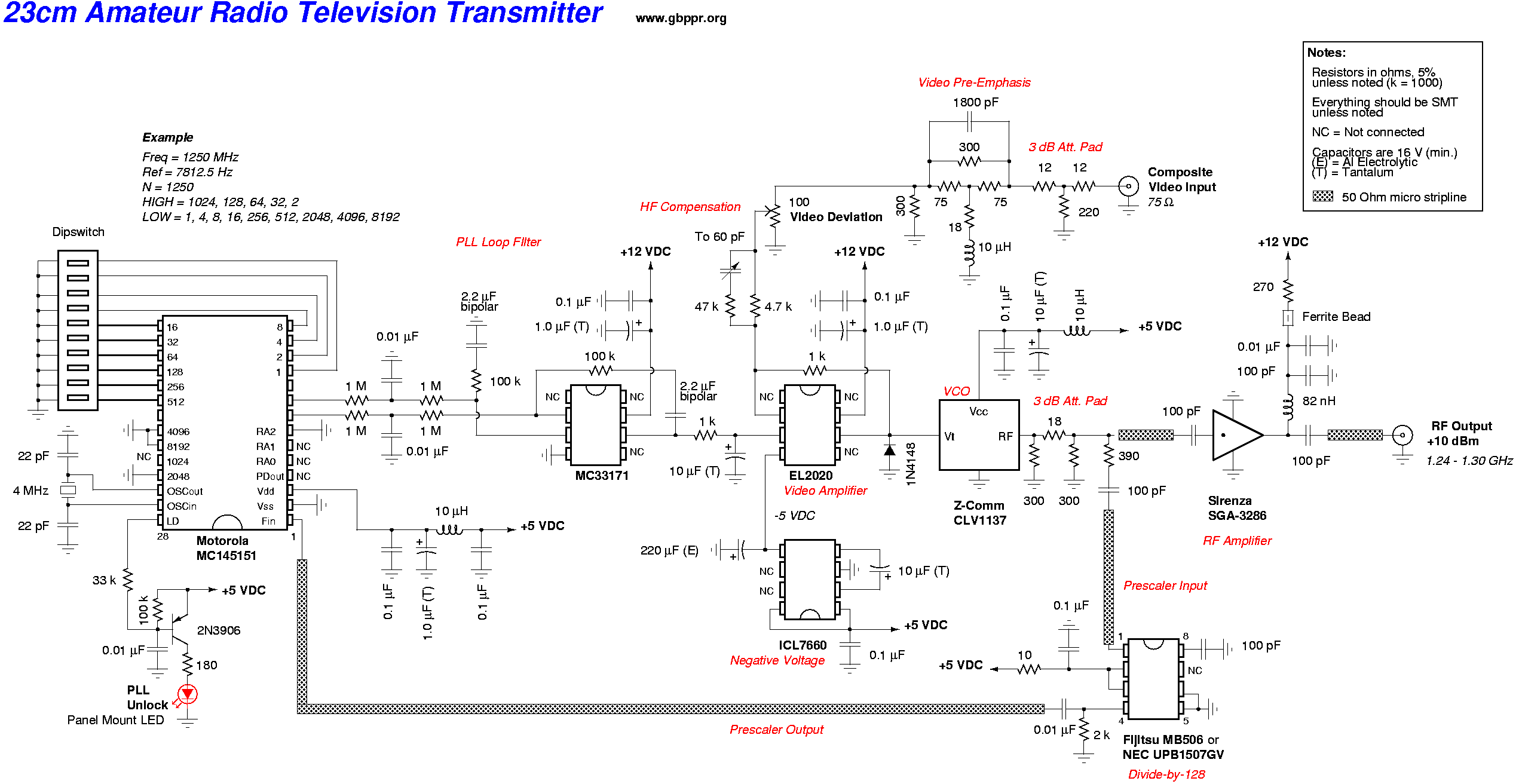
save for future revs but actually implementing a vtx is fs doable
even in the 90s lol https://www.qsl.net/n9zia/atv/23cm_atv.png
When: end of summer 2024
Why: reduce harness design complexity, improve mech stability
How: lots of JSTs, flat board
Block Diagram
Links to components are embedded in the block diagram.
To-Do List
I created this for myself to keep track of things, but feel free to comment and I will add/correct the list.
- Start compiling the headers/housings needed for these connections between the boards.
I have them below, please review at your convenience!
- VTX has built in filter, just remember to add caps at the voltage input to the board.
Will keep in mind during schematic phase.
- Compile the total current required on the 5V and 12V rails.
- Source 5V smps based on current requirement.
- Can the OSD take 5V directly from the pixhawk from the input header? If so, then we would not need the 12V-5V step down on the board, and we can use 12V for everything: cameras, osd, and vtx.
- Figure out whether or not the board 3 way camera switch board can use the common CAN circuit so we don’t have to use PWM pin.
Correct me if I am wrong, but since the 3-way switchboard does not have built-in CAN pins, I would need an external CAN controller and a unique identifier to use the CAN bus. Also, I don’t think the CAN bus can even output a PWM signal, and I don’t see any converters online aside from this one: CAN2PWM Adapter | Currawong Engineering. For this reason, I don’t think the CAN bus would be ideal to use to control the lumenier switch board.
On a side note, the lumenier switchboard also sites the following PWM values for selecting each channel:
CH1: PWM value of 1250 or below
CH2: PWM value between 1350-1750 (recommend 1500)
CH3: PWM value of 1750 and above
I am not too familiar with this representation of PWM values, but assuming that these indicate the range of values in bits that are recommended for selecting each channel, this seems to suggest that it would need 12-bits of resolution. How else would we interpret these values?
Headers/Housings
FPX Camera

1 3-pin jst-gh (1.25mm spacing) connector
1 2-pin jst-gh (1.25mm spacing) connector (optional as we tentatively do not need the OSD pins; video goes to the Lumenier switcher board)
Lumenier Camera Board

Either
1 3x5 2.5mm spacing/pitch upright male or female header to connect to the available pin holes on this board and a female or male connector on the unified vtx board respectively.
B5P-SHF-1AA JST Sales America Inc. | Connectors, Interconnects | DigiKey
This would allow for the lumenier board to be soldered directly to the board.
3 5pin jst-xh (2.5mm spacing) connectors but same configuration as 1st option.
B5B-XH-A JST Sales America Inc. | Connectors, Interconnects | DigiKey
SM03B-GHS-TB JST Sales America Inc. | Connectors, Interconnects | DigiKey
If these are chosen, the lumenier board would have separate pin headers soldered to it, and then have jst wires connect the lumenier board pin headers to these headers on the U-VTX board.
Soldering to the pads and breaking away the bottom portion to save weight.
The first and second options make it easier to plug and play, but it has added weight. Soldering option is more prone to error but has less weight. A quick Google search showed that similar solutions have similar 2.5mm pitch pins instead of jst headers.
OSD

1 6-pin jst-gh (1.25mm spacing) connector
1 4-pin jst-gh (1.25mm spacing) connector
1 3-pin jst-gh (1.25mm spacing) connector
VTX

1 6-pin JST connector (no clue about the pitch with my search), either 1.25 or 1.00mm. Need someone to confirm in-person.